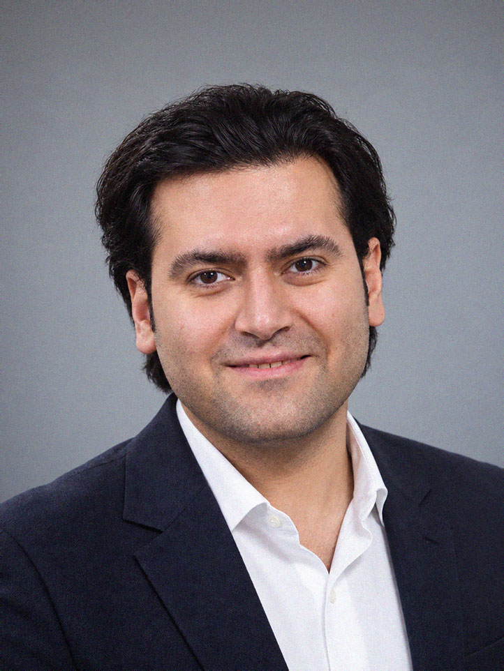
Mohammad Hossein Nikooharf, PhDMechanical & materials engineer · Arts et Métiers ParisTech

From process
to performance.

Mechanical and materials engineer. I study how manufacturing processes shape a material, measure what machines actually do, and turn that data into parts that perform as designed.

Additive and conventional processes · polymers, composites and metals · instrumentation, testing and machine learning

Paris, France · Open to R&D, engineering and research roles

01 / Beyond the layerConcept
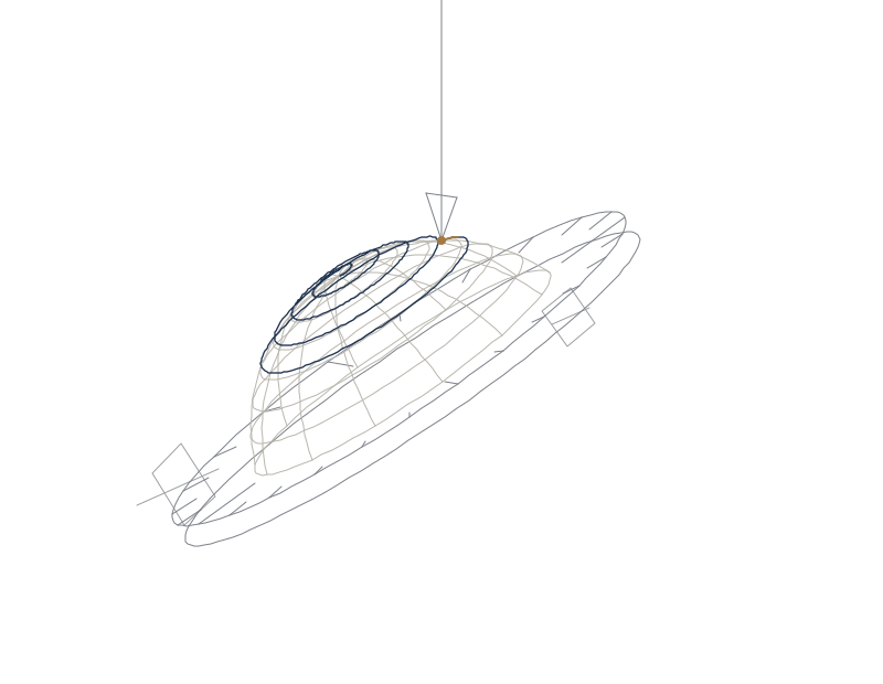
Line drawing of a five-axis deposition concept: a tilting, rotating table holds a dome while a fixed nozzle lays a spiral path that follows the curved surface.
The part moves so the tool can follow its surface.
Five-axis conformal deposition, computed live in your browser: the table tilts (A) and turns (C) so a fixed nozzle stays normal to a curved surface. A concept study, not a photograph of a machine.
PhD / 2024Arts et Métiers ParisTech
03 yearsResearch engineering at AMVALOR
07 articlesPeer-reviewed journal publications
See the work

01 / Where I contribute

One engineer.
Four ways in.

Hiring for industrialisation, materials, test equipment or research? Start with the column that matches your need.

01

Manufacturing data & instrumentation

I fit machines with sensors, synchronise the data streams and build models that predict part quality from process data, so problems show up while the part is being made.

Typical rolesSmart-manufacturing R&D · process data engineering · industrialisation and quality

The Digit.AM platform
02

Materials, processes & testing

I process and characterise polymers and composites and design the tests that qualify them: DSC, DMTA, rheometry, SEM, and mechanical tests at high strain rate, in fatigue and creep, and at cryogenic temperature.

Typical rolesMaterials engineering · process development · test and characterisation

Thermal history of printed parts
03

Mechanical design & test equipment

I design instrumented machines, fixtures and specimens in SolidWorks and CATIA V5, check them by finite-element analysis in Abaqus and verify them by dimensional metrology.

Typical rolesMechanical design · test-equipment engineering · machine R&D

Multi-axis deposition concept
04

Research & teaching

I turn open questions into testable hypotheses and published results: seven peer-reviewed articles, about 48 hours of engineering teaching, and collaborative proposals in preparation.

Typical rolesResearch engineer · postdoctoral researcher · lecturer

Publications

02 / Science, made visible

Four questions.
Four live models.

Each model below runs in your browser from first principles. They are deliberately simple, and each one says what it leaves out.

Lab 01 · Process planning

Why do printed curves look stepped, and what does tilting the tool change?

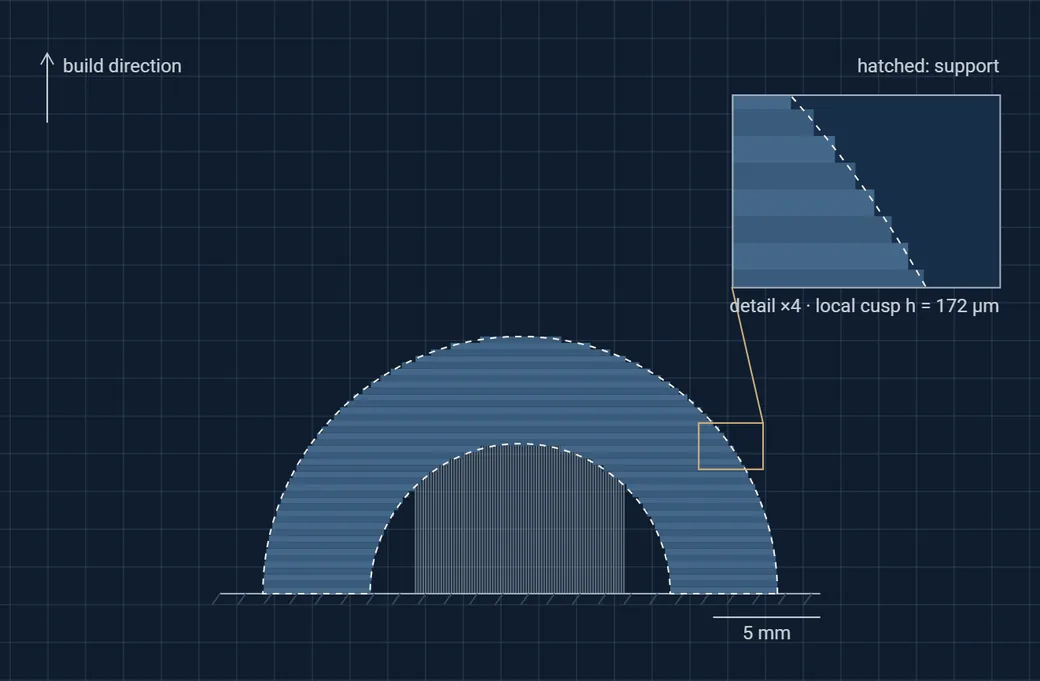
A planar printer approximates every curved or sloping surface with a staircase. The step, or cusp height, grows with the layer thickness and with how close the surface is to horizontal. For a triangular cusp, the arithmetic roughness is a quarter of the cusp height.

Down-facing surfaces more than about 45° from the vertical also need support. A multi-axis machine can instead lay its paths parallel to the surface. The staircase term vanishes, and each overhanging path rests on the side of the previous one.

h = t · |cos φ|  ·  Ra ≈ h / 4t: layer thickness · φ: angle between the surface normal and the build direction

Try this: rotate the part and watch where the roughness and the supports go, and how many layers it takes. Then switch to conformal paths.

Model and assumptions

2D section of an arch 24 mm wide and 5 mm thick. Planar layers take the cross-section at mid-height. Cusp model after Dolenc and Mäkelä; an exactly horizontal top face counts as flat. Support is needed where the surface faces down more than 45° from the vertical. Bead shape, flow, thermal distortion and machine reach are ignored; conformal mode assumes the tool can follow every surface normal.

  1. Dolenc, A., Mäkelä, I. (1994). Slicing procedures for layered manufacturing techniques. Computer-Aided Design 26(2), 119–126. doi:10.1016/0010-4485(94)90032-9
  2. Dai, C. et al. (2018). Support-free volume printing by multi-axis motion. ACM Transactions on Graphics 37(4). doi:10.1145/3197517.3201342
Lab 01 / Staircase model2D section
Static frame of the model: an arch printed in planar layers, with a stepped outer surface and supports under the inner arch.

Interactive with JavaScript: layer thickness, build orientation and planar or conformal paths.

Mean staircase roughness, Ra
—µm
Surface needing support
—
Layers or passes
—

Arch 24 mm wide · dashed: true outline · gold: tool axis

Lab 02 · Volumetric printing

Can light cure a whole object at once, with no layers at all?

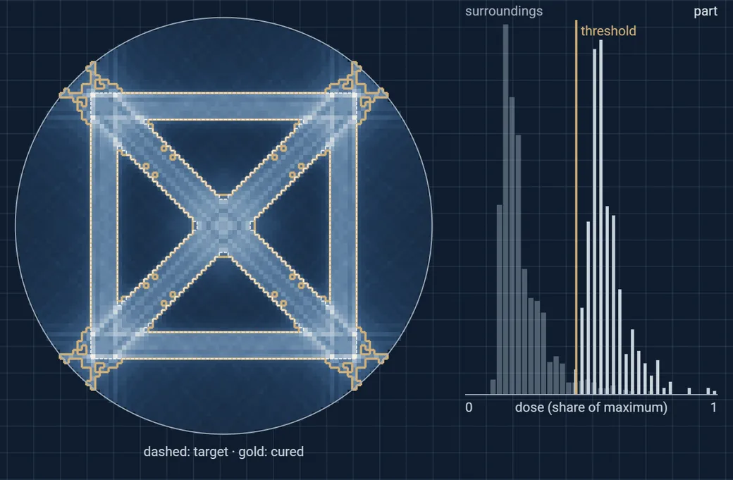
In tomographic volumetric printing, a vial of photoresin turns while a projector sends a sequence of light patterns through it. Each point receives the sum of the light that crosses it, and the resin solidifies only where this dose passes a threshold. Computing the patterns is computed tomography run backwards: filter the projections of the object, then project them into the resin.

One constraint makes it hard: light cannot be negative. Clipping the negative part of the filtered patterns blurs the dose, so parts of the object and of its surroundings end up with similar doses, and the printable window shrinks. Optimising the patterns iteratively opens it again.

D(x) = Σθ Pθ(x · nθ),  Pθ ≥ 0The dose is a sum of non-negative projections; the resin gels where it exceeds a threshold.

Try this: drop the number of angles to 8, then raise it. Switch to the wheel, whose holes are hard to keep dark, and press Optimise.

Model and assumptions

2D slice of 96 × 96 pixels through the vial. Parallel, non-absorbed light; dose adds linearly and the resin gels above a single threshold, with no diffusion of radicals or oxygen. Initial patterns: ramp-filtered projections clipped at zero. Optimisation: 40 projected-gradient steps that raise the dose where the part is under-exposed and lower it where the surroundings are over-exposed, in the spirit of object-space optimisation.

  1. Kelly, B. E. et al. (2019). Volumetric additive manufacturing via tomographic reconstruction. Science 363(6431), 1075–1079. doi:10.1126/science.aau7114
  2. Loterie, D., Delrot, P., Moser, C. (2020). High-resolution tomographic volumetric additive manufacturing. Nature Communications 11, 852. doi:10.1038/s41467-020-14630-4
  3. Rackson, C. M. et al. (2021). Object-space optimization of tomographic reconstructions for additive manufacturing. Additive Manufacturing 48, 102367. doi:10.1016/j.addma.2021.102367
Lab 02 / Tomographic dose96 × 96 slice
Static frame of the model: dose map of a lattice-cell slice with the target outline and the cured region, and a histogram of dose inside and outside the part.

Interactive with JavaScript: target shape, number of projection angles, threshold and pattern optimisation.

Shape fidelity (IoU)
—
Dose window
—
Optimisation steps
—

Dose window: lowest dose in the part minus highest dose around it

Lab 03 · Thin films on lattices

How deep can a line-of-sight coating reach inside a printed lattice?

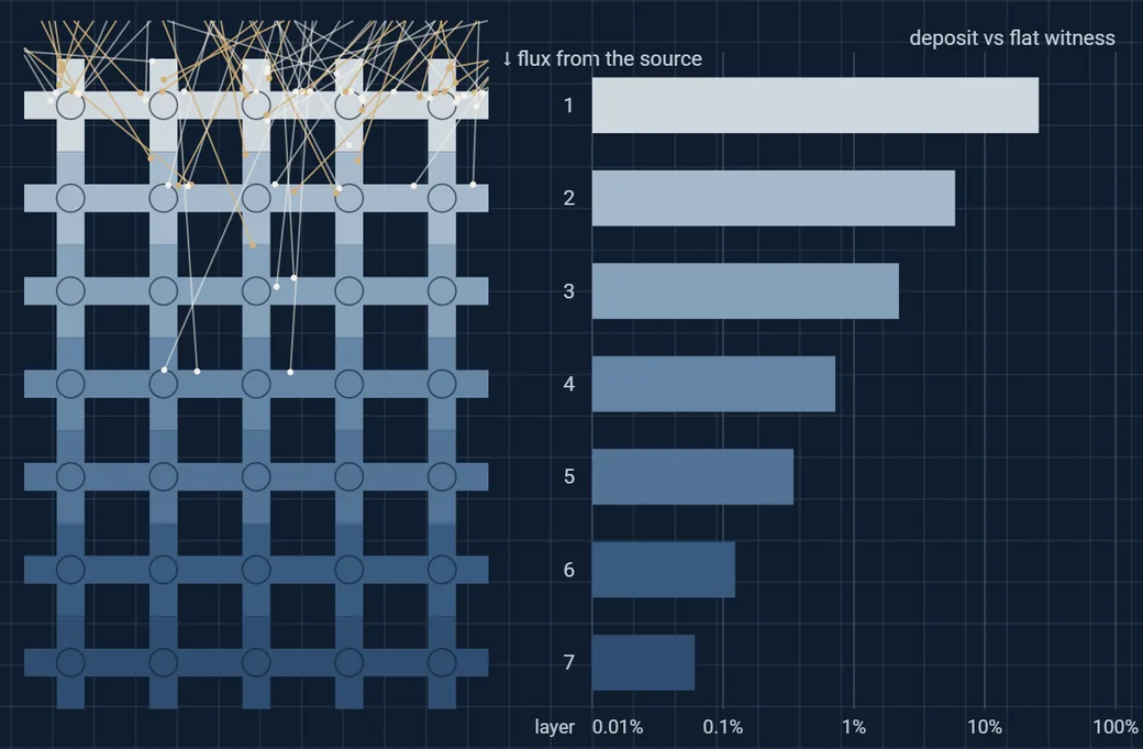
Porous implants, heat exchangers and lightweight lattices keep most of their surface inside the structure. In magnetron sputtering at about 0.5 Pa, a sputtered atom travels of the order of a centimetre between collisions, twenty or more times the pore size of a typical printed lattice. Inside the lattice each atom therefore flies in a straight line and sticks to the first strut it meets. The outer struts shadow the inner ones.

The angle of arrival matters as much as the amount. Films grown under oblique incidence form tilted, more porous columns, with different hardness and function. Measurements on a sputter-coated porous titanium implant show the same steep loss of coating with depth.

λ = kBT / (√2 π d² p) ≈ 1–2 cm at 0.5 PaMean free path from kinetic theory, far larger than pores of 0.3–1 mm: transport inside the lattice is ballistic.

Try this: make the flux more directional, thicken the struts, then tilt the specimen and let it turn. Watch the second and third layers.

Model and assumptions

3D simple cubic lattice of round struts, cell size 1, seven cell layers. Ballistic transport with sticking coefficient 1, no re-emission, resputtering or gas scattering inside the lattice. Flux ∝ cosnθ about the source axis, 60,000 trajectories. Deposit per unit strut surface, node overlaps not removed, relative to a flat witness facing the source. Check: rays parallel to the struts are captured by 2D − D² of the area, as geometry requires.

  1. Van Aeken, K., Mahieu, S., Depla, D. (2008). The metal flux from a rotating cylindrical magnetron: a Monte Carlo simulation. Journal of Physics D 41, 205307. doi:10.1088/0022-3727/41/20/205307
  2. Barranco, A. et al. (2016). Perspectives on oblique angle deposition of thin films. Progress in Materials Science 76, 59–153. doi:10.1016/j.pmatsci.2015.06.003
  3. Hawkeye, M. M., Brett, M. J. (2007). Glancing angle deposition. Journal of Vacuum Science & Technology A 25(5), 1317–1335. doi:10.1116/1.2764082
  4. Wang, P. et al. (2024). Novel nano-thin amorphous Ta-coating on 3D-printed porous TC4 implant. Materials & Design 242, 112986. doi:10.1016/j.matdes.2024.112986
Lab 03 / Ballistic deposition3D cubic lattice
Static frame of the model: front view of a strut lattice coloured by deposit, fading with depth, and a bar chart of deposit per layer on a logarithmic scale.

Interactive with JavaScript: strut size, flux directionality, specimen tilt and rotation.

Layer 1, vs flat witness
—
Layer 2, vs layer 1
—
Layer 3, vs layer 1
—
Arriving at 45° or more
—

Front view of three cells · colour: deposit per unit strut surface, log scale · gold: arrival at 45° or more

Lab 04 · Design of experiments

How many trials does it take to find a process window?

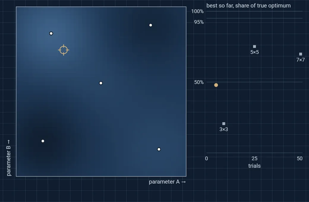
A full grid of experiments grows exponentially with the number of parameters, and a coarse grid can step right over a narrow optimum. Bayesian optimisation fits a Gaussian-process model to the trials run so far. The model gives a prediction and an uncertainty everywhere, and the next trial goes where the expected improvement is largest.

The same logic applies to print speed and temperature, deposition pressure, heat-treatment schedules or the settings of a test rig: spend each expensive experiment where it teaches the most. Here the optimum is a narrow ridge along which the two parameters interact, the situation where one-factor-at-a-time studies fail.

xnext = arg max E[ max(0, f(x) − f*) ]Expected improvement over the best result so far, under the Gaussian-process posterior.

Try this: press “Run five trials” twice and compare the gold curve with the full grids. Then switch to Uncertainty to see why the model explores.

Model and assumptions

The response is synthetic: a stand-in with an interacting main optimum and a broad side optimum, plus 2% measurement noise. It is not measured data. Squared-exponential kernel, length scale chosen by marginal likelihood among six values, five space-filling starting trials, expected improvement evaluated on a 41 × 41 grid. In 14 of 20 noise sequences the method reached 95% of the optimum, after a median of 17 trials; in the other 6 it was still exploring the side optimum after 40 trials. Full grids of 3 × 3, 5 × 5 and 10 × 10 trials reach 21%, 75% and 86% of the optimum.

  1. Jones, D. R., Schonlau, M., Welch, W. J. (1998). Efficient global optimization of expensive black-box functions. Journal of Global Optimization 13, 455–492. doi:10.1023/A:1008306431147
  2. Shahriari, B. et al. (2016). Taking the human out of the loop: a review of Bayesian optimization. Proceedings of the IEEE 104(1), 148–175. doi:10.1109/JPROC.2015.2494218
  3. Rasmussen, C. E., Williams, C. K. I. (2006). Gaussian Processes for Machine Learning. MIT Press.
Lab 04 / Bayesian optimisationSynthetic response
Static frame of the model: Gaussian-process prediction map over two parameters with trial points, and a convergence chart compared with full grids.

Interactive with JavaScript: run trials one at a time or five at a time, and switch between prediction and uncertainty.

Trials run
—
Best so far, share of the optimum
—
Fitted length scale
—

White: trials · gold ring: next suggestion · grey squares: full grids of 9, 25 and 49 trials

03 / Selected work

Real machines.
Measured results.

Evidence from my doctoral and research-engineering work at Arts et Métiers, with the photographs and data behind it.

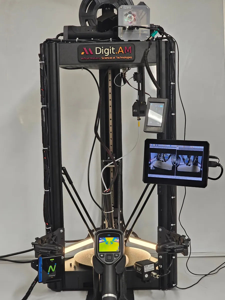
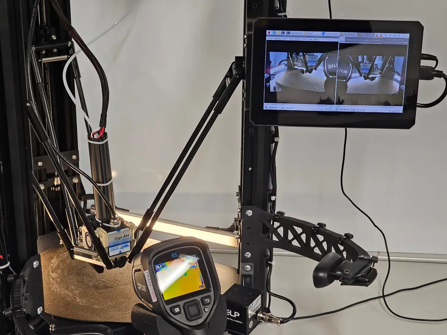
Front view of the Digit.AM delta printer: control screen with two live camera views, a thermal camera, cameras on side arms and a sensor on the effector.
Digit.AM, a retrofitted delta printer
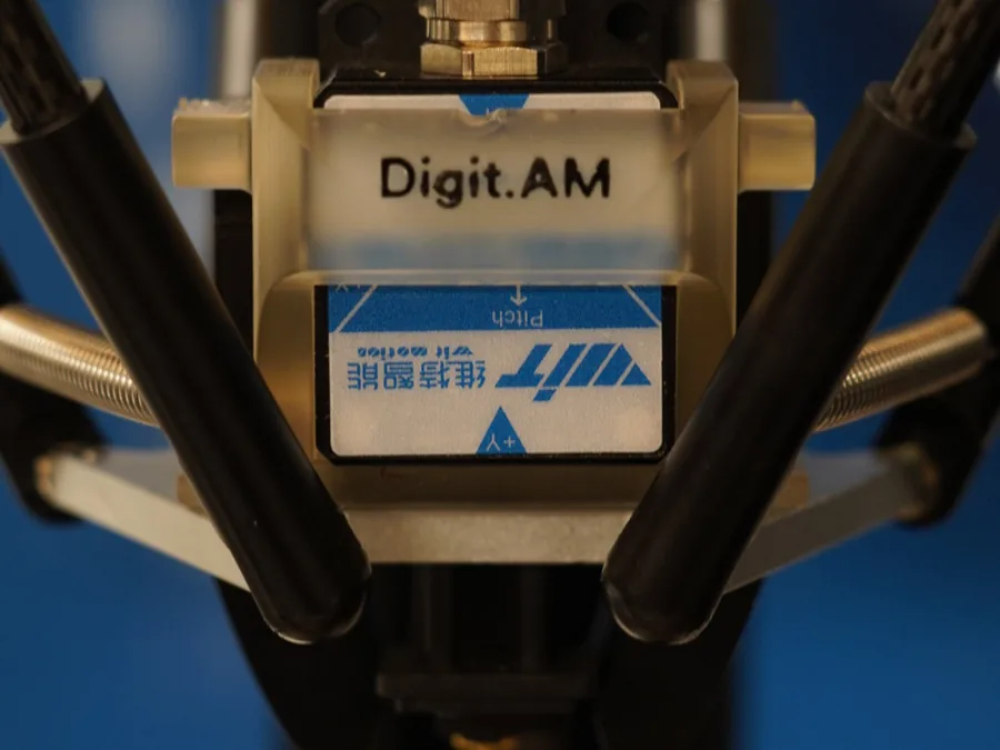
Close-up of the ten-axis inertial sensor mounted on the Digit.AM effector, between the delta arms.
Inertial sensor on the effector
The effector above the build plate, the thermal camera, and the control screen showing live views from two cameras.
Live views from two of the cameras
01 / Instrumentation and machine learning2022–2025

A printer that measures its own motion.

I retrofitted a commercial delta printer into Digit.AM. A Raspberry Pi listens to the printer’s mainboard without ever sending it commands, and timestamps and synchronises every stream: a ten-axis inertial sensor on the print head, standard, macro and thermal cameras, power consumption and ambient temperature (Progress in Additive Manufacturing, 2025). Features extracted from the nozzle’s motion then train models that predict each part’s strength, ductility and geometric deviation (The International Journal of Advanced Manufacturing Technology, 2026).

  • Twenty-four PLA specimens, printed at seven speeds from 50 to 200 mm/s: XGBoost predicted the held-out specimens with R² of 0.97 for failure stress, 0.93 for failure strain and 0.95 for scan-to-CAD deviation.
  • Micrographs tie the defects to the motion. At corners the nozzle decelerates while the flow continues, overfilling the edge; at 200 mm/s, elongated lack-of-fusion voids open between rasters and between layers. In the model without nominal speed, the variability of X-axis acceleration alone carries about 62% of the importance.
  • Leave-one-out validation is stricter. Measured kinematics still beat a speed-only model for strength and ductility, but not for geometry, where nominal speed alone does better. Three specimens printed at 225 mm/s, outside the training range, were predicted with R² above 0.90, an indicative check.
Measured motion versus nominal speed
R² of XGBoost models, three targets and three sets of inputsDot plot of R squared. Failure stress: kinematics 0.92 leave-one-out and 0.97 hold-out; kinematics plus speed 0.94 and 0.98; speed only 0.89 and 0.93. Failure strain: 0.93 and 0.93; 0.94 and 0.96; speed only 0.87 and 0.92. Scan-to-CAD deviation: 0.79 and 0.95; 0.83 and 0.96; speed only 0.87 and 0.91.leave-one-out, 24 specimens80/20 hold-outFailure stressMeasured kinematics0.920.97Kinematics + speed0.940.98Nominal speed only0.890.93Failure strainMeasured kinematics0.93Kinematics + speed0.940.96Nominal speed only0.870.92Scan-to-CAD deviationMeasured kinematics0.790.95Kinematics + speed0.830.96Nominal speed only0.870.910.750.800.850.900.951.00R²
R² of the XGBoost models. Filled dots: leave-one-out over all 24 specimens; open dots: 80/20 hold-out. Redrawn from Table 1 of the 2026 article.
02 / Process physics2022–2024

Every new layer rewrites the material below.

Two thermocouples embedded at different heights of a printed PLA specimen record what each pass of the nozzle does to the material underneath. Read against the filament’s DSC, the traces show which layers stay mobile long enough to bond, and which may crystallise.

  • Layers pass about every 17.5 s. The lower probe is reheated above the glass transition by six successive passes, each peak lower than the last.
  • Higher in the specimen, heat stored in the part keeps the material near the cold-crystallisation temperature for about 70 s.
  • The thermal history, not the nozzle set point, governs interlayer bonding and crystallinity.
Probes embedded in a printed specimenChart. Left: DSC thermogram of the PLA filament with glass transition near 61 °C, cold crystallisation peak near 102 °C and melting peak near 145 °C. Right: temperature against time at two probes embedded in a printed specimen. The lower probe is reheated above the glass transition by six successive layers, about 17.5 s apart, with decreasing peaks. The upper probe reaches 168 °C when the nozzle passes and then stays close to the cold-crystallisation temperature for about 70 s.020406080100120140160180Temperature (°C)Tg 61 °CTc 102 °CTm 145 °C-0.4-0.20.00.2Heat flow (W/g), exo →DSC, PLA filament0306090120150180Time (s)Probes embedded in a printed specimenlower probeupper probe
Probes embedded in a printed specimenChart. Left: DSC thermogram of the PLA filament with glass transition near 61 °C, cold crystallisation peak near 102 °C and melting peak near 145 °C. Right: temperature against time at two probes embedded in a printed specimen. The lower probe is reheated above the glass transition by six successive layers, about 17.5 s apart, with decreasing peaks. The upper probe reaches 168 °C when the nozzle passes and then stays close to the cold-crystallisation temperature for about 70 s.04080120160Temperature (°C)Tg 61 °CTc 102 °CTm 145 °C-0.40.2W/g, exo →DSC060120180Time (s)Probes in a printed specimenlower probeupper probe
Move along the time axis to read both probes and the material state implied by the DSC. Data digitised from the original thesis plots, one printing condition.
Glass-fibre polypropylene, measured
Quasi-static tensile strength of GF50-PP at 20 °C and −70 °CBar chart. Quasi-static tensile strength at 20 °C and minus 70 °C, for specimens cut at 0, 45 and 90 degrees to the mould flow: 0 degrees 124.6 and 168.9 MPa, 45 degrees 120.2 and 158.3 MPa, 90 degrees 137.0 and 156.4 MPa.20 °C−70 °CStrength, quasi-static (MPa)0601201801251690°12015845°13715690°angle to the mould flowRise in GF50-PP failure stress from quasi-static loading to 100 s⁻¹Bar chart. Increase in failure stress from quasi-static loading to 100 per second: 45 degrees plus 50 percent at 20 °C and plus 30 percent at minus 70 °C; 90 degrees plus 51 percent and plus 53 percent.Failure stress gain at 100 s⁻¹0%+20%+40%+60%+50%+30%45°+51%+53%90°angle to the mould flow
Quasi-static tensile strength of specimens cut at three angles to the mould flow (Composite Structures, 2021, Table 4), and rise in failure stress from quasi-static loading (0.001 s⁻¹) to 100 s⁻¹ (Applied Composite Materials, 2022). Redrawn from the published values.
03 / Composite materials2020–2021

Composites under cold and fast loading.

At the PIMM laboratory, through AMVALOR and Arts et Métiers, I made glass-fibre polypropylene plates by thermocompression (GF50-PP: 50 wt% of glass fibres about 4 cm long, porosity below 1%) and characterised their mechanical and physicochemical behaviour, in a research project funded by GTT. The material is intended for natural-gas and hydrogen storage vessels.

  • At −70 °C the composite is about 50% stiffer, from about 8 to 12.5 GPa, and 14 to 36% stronger than at 20 °C, with the same strain at failure (Composite Structures, 2021).
  • For specimens cut at 45° and 90° to the mould flow, failure stress rises by 30 to 53% from quasi-static loading to 100 s⁻¹. The fibre–matrix interface behaves viscously, so damage starts later at high rates (Applied Composite Materials, 2022 and 2023).
  • SEM identifies three damage mechanisms: fibre–matrix debonding, matrix cracking and pseudo-delamination between fibre bundles.
  • Through a thermocompressed plate, crystallinity, fibre accumulation and porosity compete: the core is more crystalline and stiffer in flexure, yet tensile tests show no significant difference in stiffness (Polymer Composites, 2021).
Read the Composite Structures article

04 / What I’m building next

Open problems.
Looking for partners.

Four projects I am scoping with academic and industrial partners. Each starts from a measurable gap. If one meets a problem you have, let’s talk, under a confidentiality agreement if needed.

Feasibility study

A quality record for every printed part.

Printed polymer parts, including high-temperature PEEK implants, inherit their crystallinity, interlayer strength and accuracy from a thermal and motion history that differs from one part to the next. Aim: release each part on its own recorded process data, with predicted properties, rather than on batch sampling.

Relevant tomedical devices · aerospace · tooling

Related: thermal history
Research proposal in preparation

Coating the inside of printed lattices.

Porous titanium implants have most of their surface inside the lattice, where line-of-sight coatings arrive thin and oblique. Aim: a validated model, from the deposition chamber down to each strut, that predicts film thickness and microstructure, and design rules for lattices that can be coated.

Relevant toorthopaedic and veterinary implants · heat exchangers · coating suppliers

Related: Lab 03
Feasibility study

Printed bones that behave like bone.

Surgeons rehearse on printed anatomical models that look right but do not drill, tap or hold a screw like bone. Aim: tune the internal architecture of printed models until they match real bone on these functional tests.

Relevant tosurgical training · medical and veterinary device makers

Related: Lab 04
Conceptual design

Multi-axis and hybrid deposition.

Combining a gantry printer with robotic handling of the part lets material follow curved surfaces and load paths without support. Aim: a compact, instrumented cell for conformal deposition with in-process measurement.

Relevant tomachine builders · research laboratories · repair and coating of curved parts

Related: Lab 01

These projects are at an early stage and are described here only in outline.

Discuss a project
Portrait of Mohammad Hossein Nikooharf
Based in Paris. Driven by curiosity.

05 / The person behind the work

At home in the lab.
And in the code.

I am a mechanical and materials engineer with a PhD from Arts et Métiers ParisTech. My work sits at the meeting point of manufacturing processes, material behaviour and data: I instrument processes, run designed experiments and build models that predict part quality before the part is made.

I work from first principles: state the assumptions, estimate the order of magnitude, then measure. I am equally at ease on the machine, in the test laboratory and in a Python script, and I write results up for peer-reviewed journals.

PhD, Arts et Métiers ParisTech · Nominated for the Pierre Bézier thesis prize 2025.

Persian · native   /   French & English · C1

06 / Expertise

Across disciplines.
Close to the detail.

The tools and methods I bring to research and engineering.

01

Additive manufacturing

Fused filament fabrication is my core process: instrumented platforms, process-parameter optimisation by design of experiments, dimensional stability and mechanical performance of printed structures. Hands-on practice with laser powder-bed fusion (SLM), stereolithography (SLA) and selective laser sintering (SLS).

  • FFF
  • SLM
  • SLA
  • SLS
  • Design of experiments
  • Process optimisation
02

Polymer and composite materials

Processing and characterisation of thermoplastic composites: thermocompression, injection moulding, rotational moulding and RIM, filament winding. Mechanical testing at high strain rate, in fatigue and creep, and at cryogenic temperature; DSC, DMTA, rheometry, SEM and FTIR analysis.

  • GF/PP composites
  • Thermocompression
  • Injection moulding
  • Filament winding
  • Mechanical testing
  • DSC / DMTA / SEM
03

Design and simulation

Mechanical design in SolidWorks and CATIA V5, with design for additive and moulding processes. Finite-element analysis in Abaqus for forming and structural problems. Dimensional metrology with coordinate measuring machines, 3D scanning and profilometry; FMEA.

  • SolidWorks
  • CATIA V5
  • Abaqus
  • CMM / 3D scanning
  • FMEA
04

Data and machine learning for manufacturing

Multi-sensor data acquisition and synchronisation, feature engineering from process kinematics, machine-learning and deep-learning models for quality prediction and fault detection. Python (NumPy, pandas) and MATLAB. Certified in supervised machine learning and advanced learning algorithms (DeepLearning.AI, Stanford Online).

  • Python
  • MATLAB
  • Sensor data
  • Machine learning
  • Deep learning
  • Fault detection

07 / Experience

A foundation in research.
A focus on application.

  1. Oct 2022 to Dec 2025

    Research engineer

    AMVALOR, Arts et Métiers ParisTech, Paris

    • Doctoral research (2022 to 2024) on the Digit.AM instrumented fused filament fabrication platform: multi-sensor acquisition during printing, machine-learning prediction of geometrical accuracy and mechanical properties, fault detection.
    • Post-doctoral research (2025): writing up the group's latest journal articles and contributing to the laboratory's ongoing projects.
    • Teaching: about 48 hours of lectures and practical classes for second-year engineering students (design process and innovation, additive manufacturing).
  2. Oct 2020 to Jun 2021

    Research assistant, master's project

    AMVALOR, PIMM laboratory (CNRS UMR 8006), Arts et Métiers ParisTech, Paris

    • Glass-fibre polypropylene composite plates (GF50-PP) made by thermocompression, for a research project funded by GTT.
    • Mechanical testing at high strain rate, in fatigue and creep, and at cryogenic temperature; physicochemical characterisation by DSC, DMTA, rheometry, SEM and FTIR.
    • Results published in Composite Structures, Polymer Composites and Applied Composite Materials.
  3. Jun to Sep 2016

    Engineering intern

    IKCO Automotive Group, with the University of Tehran

    • Deep drawing of bake-hardenable steel sheet: surface roughness study and forming simulation in Abaqus.

08 / Education

Degrees and certificates

  1. 2022 to 2024

    PhD in mechanical engineering, fabrication processes

    Arts et Métiers ParisTech (ENSAM), Paris

    Thesis: multi-scale intelligent optimisation of the dimensional stability and mechanical properties of additively manufactured (FFF) structures. Defended in December 2024; nominated for the Pierre Bézier thesis prize 2025.

  2. 2019 to 2021

    Master's degree in mechanical engineering, materials and surface engineering

    Arts et Métiers, Cluny campus

  3. 2017 to 2020

    Master's degree in materials and metallurgical engineering

    Iran University of Science and Technology, Tehran

  4. 2013 to 2017

    Engineering degree in materials and metallurgical engineering

    University of Tehran

  5. 2024 and 2025

    Certificates in machine learning

    DeepLearning.AI and Stanford Online, on Coursera

09 / Publications

The work, in print.

Google Scholar
  1. Kinematics-driven machine learning framework for predictive optimization of geometrical accuracy and mechanical properties in fused filament fabrication

    The International Journal of Advanced Manufacturing Technology, 2026 · doi:10.1007/s00170-026-19039-9

  2. Toward advance/digitalized FFF: real-time multimodal synchronized data acquisition and ML/DL-driven process optimization

    Progress in Additive Manufacturing, 2025 · doi:10.1007/s40964-025-01187-1 · Open access

  3. Machine learning in polymer additive manufacturing: a review

    International Journal of Material Forming, 2024 · doi:10.1007/s12289-024-01854-8 · Open access

  4. Manufacturing process effect on the mechanical properties of glass fiber/polypropylene composite under high strain rate loading: woven (W-GF-PP) and compressed GF50-PP

    Applied Composite Materials, 2023 · doi:10.1007/s10443-023-10143-7

  5. Mechanical properties and damage behavior of polypropylene composite (GF50-PP) plate fabricated by thermocompression process under high strain rate loading at room and cryogenic temperatures

    Applied Composite Materials, 2022 · doi:10.1007/s10443-022-10047-y

  6. Multi-scale analysis of mechanical properties and damage behavior of polypropylene composite (GF50-PP) plate at room and cryogenic temperatures

    Composite Structures, 2021 · doi:10.1016/j.compstruct.2021.114713

  7. Comparison of the physicochemical, rheological, and mechanical properties of core and surface of polypropylene composite (GF50-PP) plate fabricated by thermocompression process

    Polymer Composites, 2021 · doi:10.1002/pc.26059

ORCID 0000-0002-7324-5370

10 / Start a conversation

Good engineering
starts with a
good question.

A role, an R&D challenge, a research idea or a project to discuss? I would like to hear from you.

Open to R&D, engineering and research roles · Paris region